Install the app
How to install the app on iOS
Follow along with the video below to see how to install our site as a web app on your home screen.
Note: This feature may not be available in some browsers.
You are using an out of date browser. It may not display this or other websites correctly.
You should upgrade or use an alternative browser.
You should upgrade or use an alternative browser.
APRS ..yms. radioamatööritoimintaa
- Viestiketjun aloittaja KorpiSISSI
- Aloitus PVM
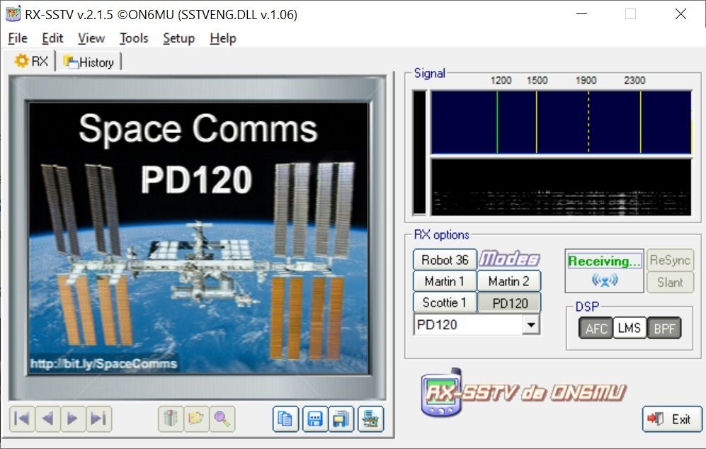
Demonstrating what engineers and scientists get up to when they are riding out the current pandemic in their homes, the ESA team has put out a series of tutorials for Windows 7 and 10, macOS, iOS and Android, Ubuntu, and, of course, the Raspberry Pi, on how to pick up and decode Slow Scan Television (SSTV) transmissions from the orbiting outpost.
Those hoping for the latest and greatest HD video should look away now: think more ZX Spectrum loading screen than Netflix 4K cinematics.
Naturally, we had a crack at making it work (using the Windows 10 instructions) and succeeded in viewing the test image after delving into the dark arts of the Windows sound mixer. Pay close attention to the instructional video on setting up the Stereo Mixer (we didn't).
Spotted the ISS in the sky yet? How about pulling out some spare kit and giving it a listen?
ESA emits a guide to picking up Slow Scan TV from the orbiting outpost
Amateur radio operators have always been at the top of their game when they’ve been hacking radios. A ham license gives you permission to open up a radio and modify it, or even to build a radio from scratch. True, as technology has advanced the opportunities for old school radio hacking have diminished, but that doesn’t mean that the new computerized radios aren’t vulnerable to the diligent ham’s tender ministrations.
A case in point: the Kenwood TH-D74A’s firmware has been dumped and partially decoded. A somewhat informal collaboration between [Hash (AG5OW)] and [Travis Goodspeed (KK4VCZ)], the process that started with [Hash]’s teardown of his radio, seen in the video below. The radio, a tri-band handy talkie with capabilities miles beyond even the most complex of the cheap imports and with a price tag to match, had a serial port and JTAG connector. A JTAGulator allowed him to probe some of the secrets, but a full exploration required spending $140 on a spare PCB for the radio and some deft work removing the BGA-packaged Flash ROM and dumping its image to disk.
[Travis] picked up the analysis from there. He found three programs within the image, including the radio’s firmware and a bunch of strings used in the radio’s UI, in both English and Japanese. The work is far from complete, but the foundation is there for further exploration and potential future firmware patches to give the radio a different feature set.
This is a great case study in reverse engineering, and it’s really worth a trip down the rabbit hole to learn more. If you’re looking for a more formal exploration of reverse engineering, you could do a lot worse than HackadayU’s “Reverse Engineering with Ghidra” course, which just wrapping up.
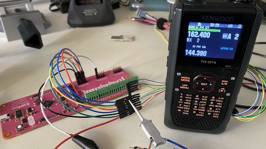
High-End Ham Radio Gives Up Its Firmware Secrets
Amateur radio operators have always been at the top of their game when they’ve been hacking radios. A ham license gives you permission to open up a radio and modify it, or even to build a rad…
Todella hieno
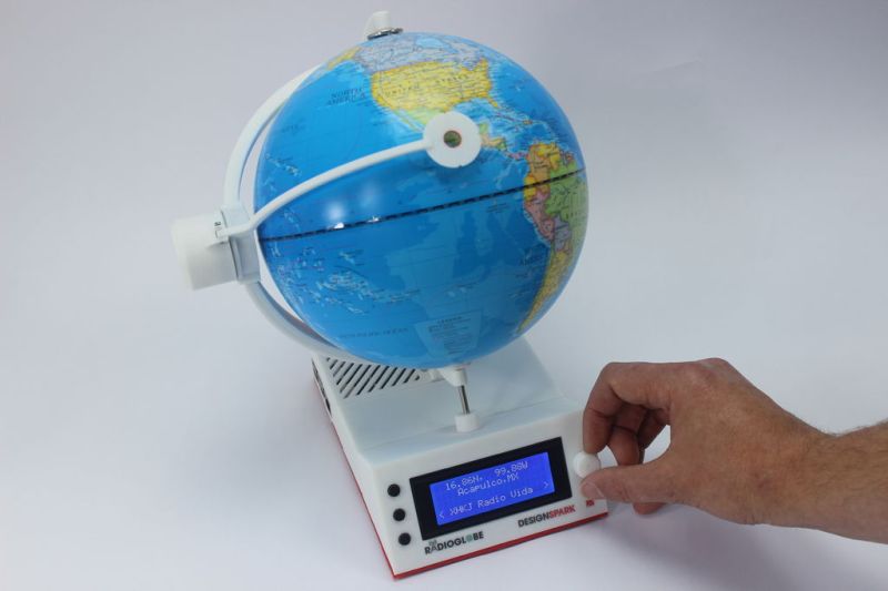

https://hackaday.com/2020/07/27/radioglobe-takes-the-world-of-internet-radio-for-a-spin/There’s no denying that the reach and variety of internet radio is super cool. The problem is that none of the available interfaces really give the enormity of the thing the justice it deserves. We long for a more physical and satisfying interface for tuning in stations from around the globe, and [Jude] has made just the thing.
RadioGlobe lets the user tune in over 2000 stations from around the world by spinning a real globe. It works by using two absolute rotary encoders that each have a whopping 1024 positions available. One encoder is stuck into the South Pole, and it reads the lines of longitude as the user spins the globe.
The other encoder is on the left side of the globe, and reads whatever latitude is focused in the reticle. Both encoder are connected to a Raspberry Pi 4, though if you want to replicate this open-source project using the incredibly detailed instructions, he says a Raspberry Pi 3 B+ will work, too.
In the base there’s an LCD that shows the coordinates, the city, and the station ID. Other stations in the area are tune-able with the jog wheel on the base. There’s also an RGB LED that blinks red while the station is being tuned in, and turns green when it’s done. We totally dig the clean and minimalist look of this build — especially the surprise transparent bottom panel that lets you see all the guts.
There are three videos after the break – a short demo that gives you the gist of how it works, a longer demonstration, and a nice explanation of absolute rotary encoders. Those are just the tip of the iceberg, because [Jude] kept a daily vlog of the build.
Maybe you just long for a web radio that dials in vintage appeal. This antique internet radio has a lot of features, but you wouldn’t know it from the outside.
Onkohan venäläiset herättäneet tikan uudestaan henkiin? Eilen kuuntelin ja tallensin joutessani puolalaista S11a numeroaseman lähetystä, niin muutama minuutti lähetyksen alkamisesta alkoi kuulua vaimeaa naputtavaa ääntä joka nopeasti voimistui takovaksi paukutukseksi ja siirtyi kokonaan tuon numeroita lähettävän taajuuden päälle ja sitä kesti noin puoli minuuttia.
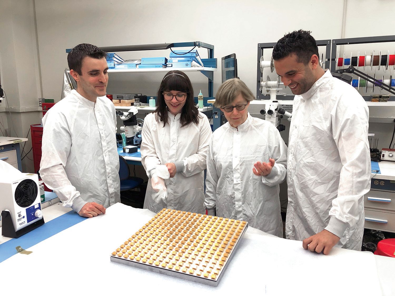
Ultimately, when NASA’s Jet Propulsion Laboratory (JPL), where I am a senior antenna engineer, began to seriously consider a Europa lander mission, we realized that the antenna was the limiting factor. The antenna needs to maintain a direct-to-Earth link across more than 550 million miles (900 million km) when Earth and Jupiter are at their point of greatest separation. The antenna must be radiation-hardened enough to survive an onslaught of ionizing particles from Jupiter, and it cannot be so heavy or so large that it would imperil the lander during takeoff and landing. One colleague, when we laid out the challenge in front of us, called it impossible. We built such an antenna anyway—and although it was designed for Europa, it is a revolutionary enough design that we’re already successfully implementing it in future missions for other destinations in the solar system
Traditionally, landers (and rovers) designed for Mars missions rely on relay orbiters with high data rates to get scientific data back to Earth in a timely manner. These orbiters, such as the Mars Reconnaissance Orbiter and Mars Odyssey, have large, parabolic antennas that use large amounts of power, on the order of 100 watts, to communicate with Earth. While the Perseverance and Curiosity rovers also have direct-to-Earth antennas, they are small, use less power (about 25 W), and are not very efficient. These antennas are mostly used for transmitting the rover’s status and other low-data updates. These existing direct-to-Earth antennas simply aren’t up to the task of communicating all the way from Europa.
So, to reiterate the challenge: The antenna cannot be large, because then the lander will be too heavy. It cannot be inefficient for the same reason, because requiring more power would necessitate bulky power systems instead. And it needs to survive exposure to a brutal amount of radiation from Jupiter. This last point requires that the antenna must be mostly, if not entirely, made out of metal, because metals are more resistant to ionizing radiation.
The antenna we ultimately developed depends on a key innovation: The antenna is made up of circularly polarized, aluminum-only unit cells—more on this in a moment—that can each send and receive on X-band frequencies (specifically, 7.145 to 7.19 gigahertz for the uplink and 8.4 to 8.45 GHz for the downlink). The entire antenna is an array of these unit cells, 32 on a side or 1,024 in total. The antenna is 32.5 by 32.5 inches (82.5 by 82.5 centimeters), allowing it to fit on top of a modestly sized lander, and it can achieve a downlink rate to Earth of 33 kilobits per second at 80 percent efficiency.
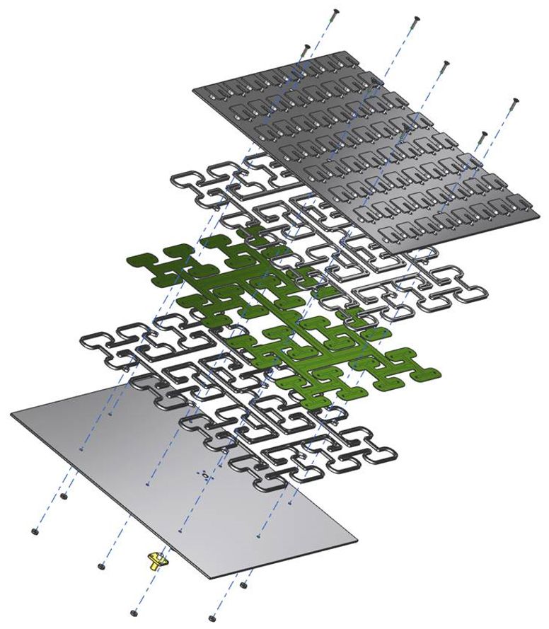
Each unit cell, as mentioned, is entirely made of aluminum. Earlier antenna arrays that similarly use smaller component cells include dielectric materials like ceramic or glass to act as insulators. Unfortunately, dielectric materials are also vulnerable to Jupiter’s ionizing radiation. The radiation builds up a charge on the materials over time, and precisely because they’re insulators there’s nowhere for that charge to go—until it’s ultimately released in a hardware-damaging electrostatic discharge. So we can’t use them.
As mentioned before, metals are more resilient to ionizing radiation. The problem is they’re not insulators, and so an antenna constructed entirely out of metal is still at risk of an electrostatic discharge damaging its components. We worked around this problem by designing each unit cell to be fed at a single point. The “feed” is the connection between an antenna and the radio’s transmitter and receiver. Typically, circularly polarized antennas require two perpendicular feeds to control the signal generation. But with a bit of careful engineering and the use of a type of automated optimization called a genetic algorithm, we developed a precisely shaped single feed that could get the job done.
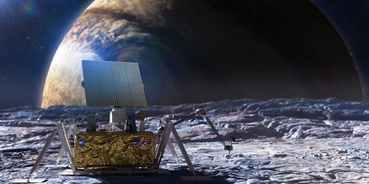
No Antenna Could Survive Europa’s Brutal, Radioactive Environment—Until Now
To explore Jupiter’s moon for signs of life, JPL developed a brand new, all-metal design
 spectrum.ieee.org
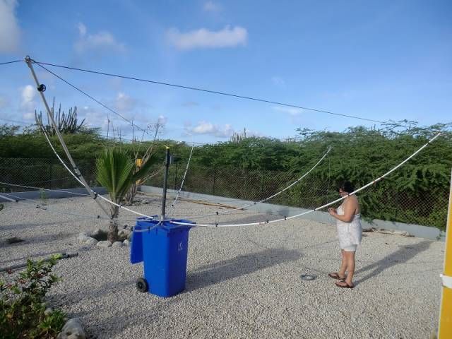
Although the antenna isn’t done, it is already working and looks impressive. There’s a lot of wire, so this probably isn’t a condo-friendly solution. The name of the antenna derives from the three wires, one tuned for 3 MHz, one for 6 MHz, and the other for 9 MHz.
The mechanical construction is impressive, with springs and pulleys. The wire used is actually MIG welding wire which is cheap and durable. Supposedly, the antenna has already performed well with an average receiver, but we didn’t get to hear it ourselves. Maybe in the next video.
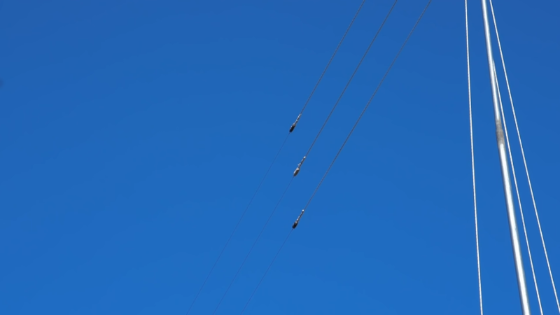
A 3-6-9 Antenna Pulls In The Signals
Every time we see a dispatch from [Mr. Carlson], we imagine it is being beamed from his orbital station packed full of vintage radio gear. We are certain the reality is more terrestrial, but if we …
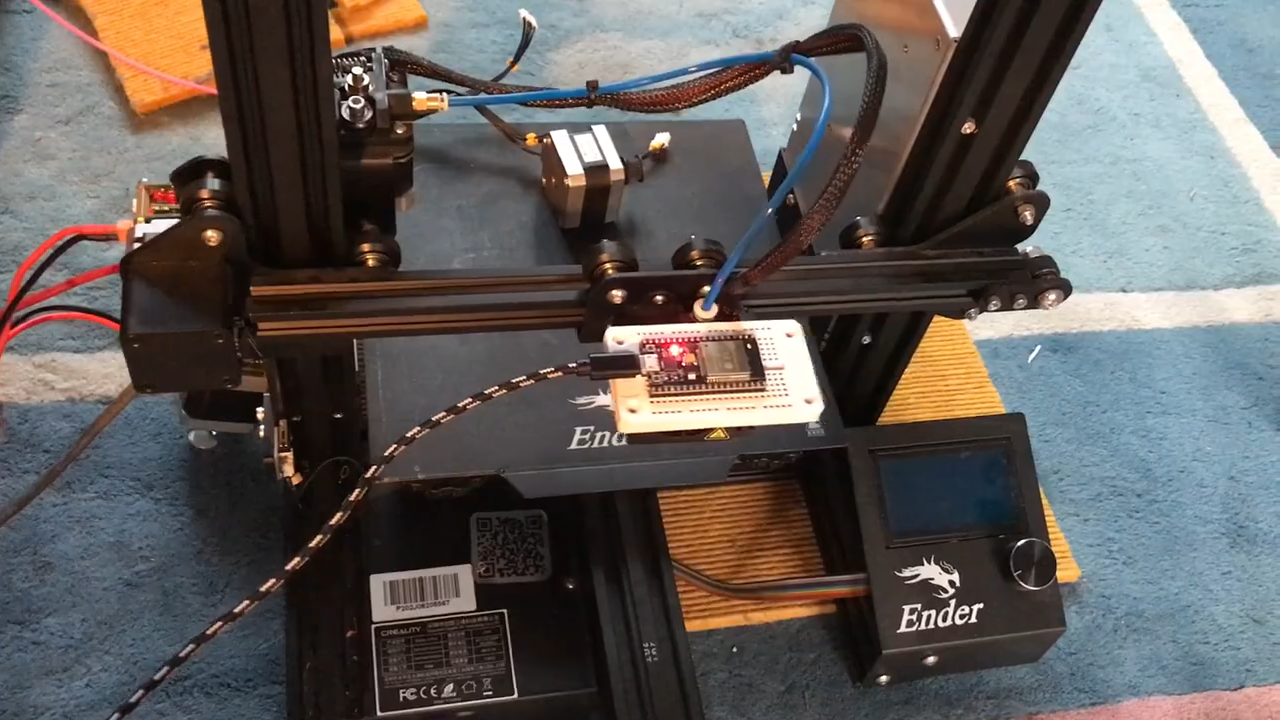
Visualizing WiFi With A Converted 3D Printer
We all know we live in a soup of electromagnetic radiation, everything from AM radio broadcasts to cosmic rays. Some of it is useful, some is a nuisance, but all of it is invisible. We know it̵…
For the first time ever we bounced a LoRa message off the moon on October 5th 2021, using the Dwingeloo radio telescope. This first was achieved by a team consisting of Jan van Muijlwijk (CAMRAS, PA3FXB), Tammo Jan Dijkema (CAMRAS), Frank Zeppenfeldt (ESA, PD0AP) and Thomas Telkamp (Lacuna Space, PA8Z). The signal traveled an amazing distance of 730,360 km, which to our knowledge is the furthest distance a LoRa modulated message has ever traveled.
For a short moment the entire message was in space, in between the Earth and the Moon. We transmitted the signal with a Semtech LR1110 RF transceiver chip (in the 430-440 Mhz amateur band), amplified to 350 Watt, using the 25 meter dish of the telescope. Then, 2.44 seconds later, it was received by the same chip. One of the messages even contained a full LoRaWAN frame.
Nicolas Sornin, co-inventor of LoRa, told us: "This is a fantastic experiment, I had never dreamed that one day a LoRa message would travel all the way to the moon and back! I am impressed by the quality of the data captured, this dataset is going to become a classic for radiocommunications and signal processing students. A big thumbs up to the team and CAMRAS foundation for making this possible".
The Dwingeloo radio telescope, operated by the CAMRAS foundation, has a history of being used in amateur radio experiments and is now often used for moon bounces, but this was the first time a data message was bounced using a small RF chip. This telescope was commissioned in 1956, and played an important role in the early exploration of the structure of the Milky Way using 21 cm hydrogen radiation.
With the LR1110 chip we also measured the round trip time of the message, as well as the frequency offset due to Doppler caused by the relative motion of the Earth and the Moon. From the round trip time we calculated the distance to the moon. Both distance and frequency offset matched very well with predicted values calculated using NASA's JPL Horizons ephemeris system.
In addition to the LoRa chips, we used an SDR (Software Defined Radio) to capture both the transmitted and received signal for further analysis. These measurements together with analysis notebooks will be published as open data. As a preview, this is a Delay-Doppler plot of the received signal, essentially showing a radar image of the moon, the ultimate example of joint communications and sensing.

First LoRa message bounced off the moon
Harwell UK (SPX) Nov 29, 2021 - For the first time ever we bounced a LoRa message off the moon on October 5th 2021, using the Dwingeloo radio telescope. This first was achieved by a team consisting of Jan van Muijlwijk (CAMRAS, PA
www.spacedaily.com
Sähkötyksen opetteluun Learn Morse Code Online myös suomenkielisenä versiona

American Radio Relay League vastaanottoharjoitukset,
 www.arrl.org

American Radio Relay League vastaanottoharjoitukset,
Code Practice Files
The American Radio Relay League (ARRL) is the national association for amateur radio, connecting hams around the U.S. with news, information and resources.
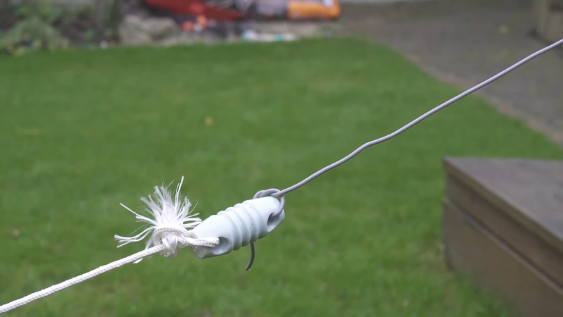
Ham Antenna Fits Almost Anywhere
[G3OJV] knows the pain of trying to operate a ham radio transmitter on a small lot. His recent video shows how to put up a workable basic HF antenna in a small backyard. The center of the system is…
Laitan tänne koska tämä on niin lähellä mitä me tehtäsiin vastaavassa tilanteessa.

 www.theregister.com
Limited communication is being restored in Tonga through satellite, high-frequency radio and motorboat after a violent underwater volcano severed a fiber-optic cable connecting the remote island to the world.
The Hunga Tonga-Hunga Ha'apai underwater eruption – equivalent to a 10 megaton blast, it's estimated – on Saturday damaged two cables that were the backbones of international and domestic communications in Tonga.
The internet still remains cut off though communications is being restored through other means, the government of Tonga said in its first official statement, posted on Twitter by the Tonga Embassy in Tokyo.
Tonga has deployed patrol boats as the first step in restoring communication across Tonga's islands.
As of Tuesday, limited communication had been established between the main island of Tongatapu, where the capital Nuku'alofa is located, and the nearby Vava'u and Ha'apai island chains through satellite phone and HF radio.
"The two communication providers are working on satellite options to restore some services including the Internet," the government said in its statement.
The first images of the true extent of damage caused by the volcano started emerging on Monday through images taken by surveillance planes. The Tongan government website was down as of Tuesday morning, and attempts to access the site timed out.
An investigation by one of the communications providers, Digicel, revealed that two separate undersea cables were broken. One was on the domestic cable route linking the islands in Tonga together, and the other, and perhaps more critical, was on an undersea fiber optic cable that linked Tonga to the rest of the world.

Internet's still out in Tonga with underwater cable severed
Next steps for island nation
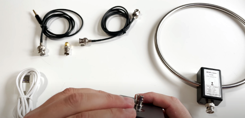
Modern ham radio operators often face restrictions on antennas. This has made small antennas more popular, despite some limitations. [Tech Minds] reviews the GA-450 indoor active HF loop antenna and finds it better than expected. You can see the video review below.
You can’t expect a little antenna to perform as well as giant skyhook. However, for such a small loop covering 3 to 30 MHz, the antenna seems to perform very well. We like that the active part of it has a rechargeable battery. Obviously, you will only want to use this antenna for receiving, but it would be a great pairing for an HF-capable software defined radio (SDR). Even just in the window sill with half gain, it was able to pick up quite a bit of signal on the 40 meter and 20 meter ham bands. According to the video, performance below 7 MHz was lackluster, but it worked nicely at higher frequencies.
The loop is directional and you can rotate the loop on the base to zero in on a particular signal. Of course, if the antenna were up in the air, it might be harder to rotate unless you work out something with a motor. If all you want to do is receive and you have a budget of under $100, this looks like it would be a nice portable option.
Affordable HF Loop Antenna Reviewed
Modern ham radio operators often face restrictions on antennas. This has made small antennas more popular, despite some limitations. [Tech Minds] reviews the GA-450 indoor active HF loop antenna an…
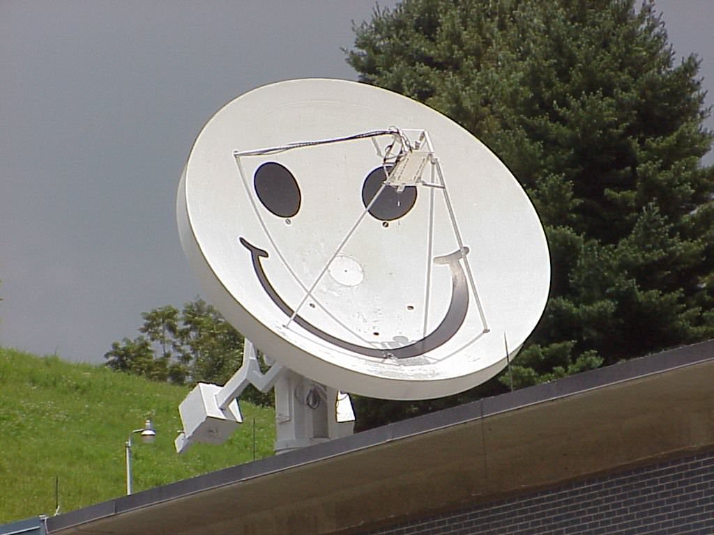
Radioamatöörit, aina pilaamassa näkymiä vehkeillänsä

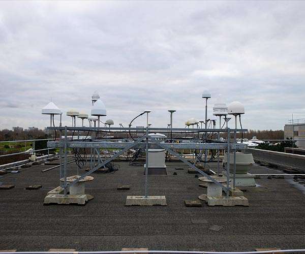
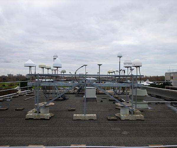
A small forest of antennas sprouts from the roof of ESA's Navigation Laboratory, based at the ESTEC technical centre in the Netherlands, which is among the most frequently satnav-fixed locations on Earth. This is also the site of the very first Galileo positioning fix, acquired back in 2014 using the first quartet of Galileo satellites.
"The antenna is a critical component of any Global Navigation Satellite System user segment, capturing power from the electromagnetic waves it receives, then converting it into electrical current to be processed by the rest of the receiver chain," explains Radio Navigation Engineer Michelangelo Albertazzi.
"Up here we have a variety of antenna designs in place - such as omnidirectional, high gain and arrays - from leading world receiver manufacturers, which acquire signals from all major global GNSS constellations, including Galileo, GPS, the Russian Glonass and China's Beidou, as well as regional systems such as Europe's EGNOS."
The NavLab is also equipped with state-of-the-art equipment to record, replay and analyze the RF signals picked up by these antennas, to help with its main goal of performing tests, analyses and characterisation of navigation systems for both ESA and external customers.
To find out more about working with ESA facilities, check our new website on the duties and resources of ESA's Directorate of Technology, Engineering and Quality.
Roof of the satnav world
Noordwijk, Netherlands (SPX) Feb 04, 2022 - A small forest of antennas sprouts from the roof of ESA's Navigation Laboratory, based at the ESTEC technical centre in the Netherlands, which is among the most frequently satnav-fixed locations on
www.spacedaily.com
Radioamatöörit liittyy tähän miten?
Radioamatöörit, aina pilaamassa näkymiä vehkeillänsä

Roof of the satnav world
Noordwijk, Netherlands (SPX) Feb 04, 2022 - A small forest of antennas sprouts from the roof of ESA's Navigation Laboratory, based at the ESTEC technical centre in the Netherlands, which is among the most frequently satnav-fixed locations onwww.spacedaily.com
vitsi, mutta ihan oikeasti, radioamatöörit tutkivat asioita samanlailla kuin ammattilaiset ja kuten ammattilaiset, heidän alueensa voivat näyttää sekamelskoilta. EsimerkkiRadioamatöörit liittyy tähän miten?
