APRS ..yms. radioamatööritoimintaa

Paljon suorituskykyä ppienellä rahalla, NanoVNA oli minulle suureksi avuksi etsittäessä antennisovittimelle oikeaa asentoa jotta mahdolisimman paljon signaalista menee antenniin ja antennille sellaista pituutta jossa sähkövirta muuttuu mahdollisimman tehokkaasti sähkämagneettiseksi säteilyksi.

Toimii HF alueelta UHF alueelle.
 
  • Tykkää
Reactions: ctg
husky_electric_xtal_set2.jpg

cs1.jpg


The crystal radio, or “crystal set”, is a radio receiving circuit that does not require an external power source to operate. Running only on energy from radio waves, crystal sets were used by many pioneers in the early days of broadcasting and wireless communications. The first commercially available crystal sets in the early 20th century were expensive and thus, DIY radio kits and building from scratch were popular alternatives. By the 1920’s, crystal radios fell out of favor as home entertainment devices but its popularity as a boys’ hobby continued into the 1970’s as kit manufacturers such as Heathkit and Eico offered crystal receivers.

Because crystal sets have neither power supplies nor amplification, they offer clean and true high-fidelity audio. The lack of power supplies means no power line noise. The lack of amplification mean no tubes and therefore, no annoying filament/heater hum, and also no transistors means free of harshness in the audio. As such, crystal radios are used by some audiophiles today.

While crystal radios are simple and fun to build, the majority of crystal sets built today are ugly in appearance, with a bunch of wires, pins, and other components all exposed on a piece of wood. In this challenge, I have decided to take it a step further to try to build a crystal radio that (1) does not look like a kid’s science fair projects and (2) looks beautiful on a display shelf. I based my design on old English crystal sets such as the Gecophone in which the set is housed in a wooden enclosure box. For the working circuit, I used the 1932 Australian “Mystery” design. Well known for its sensitivity and simplicity, and despite being popular, nobody knows exactly how the “Mystery Set” works to this day (more on this later).
 
pmp.png

block-diagram.jpg


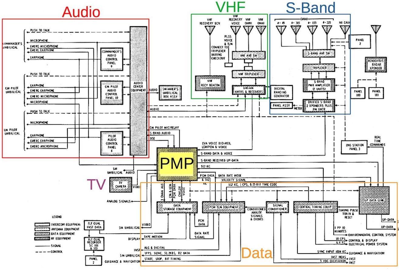
Despite what it looks like in the movies, it is hard to communicate with astronauts from Earth. There are delays, and space vehicles don’t usually have a lot of excess power. Plus everything is moving and Doppler shifting and Faraday rotating. Even today, it is tricky. But how did Apollo manage to send back TV, telemetry, and voice back in 1969? [Ken Shirriff] and friends tell us part of the story in a recent post where he looks at the Apollo premodulation processor.

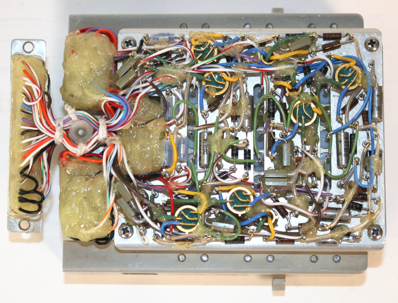
Things like weight and volume are always at a premium in a spacecraft, as is power. When you look at pictures of this solid box that weighs over 14 pounds, you’ll be amazed at how much is crammed into a relatively tiny spot. Remember, if this box was flying in 1969 it had to be built much earlier so there’s no way to expect dense ICs and modern packaging. There’s not even a printed circuit board. The components are attached to metal pegs in a point-to-point fashion. The whole thing lived near the bottom of the Command Module’s lower equipment bay.

The processor, or PMP, played a key role in multiplexing different streams in different configurations and passing them to (and from) the onboard S-band transmitter. Inside the box, [Ken] found four subassemblies nicely labeled and connected to a thin backplane. Along with discrete components, the modules also employed off-the-shelf assemblies that predated ICs and offered functions like filters or oscillators in one convenient package.

One thing that further complicated the design was the need for redundancy. For example, there are two switching regulators inside — yep, a switching regulator in a piece of gear from the 60’s — and the crew could select between the two power supplies.


We always enjoy [The History Guy] videos, although many of them aren’t much about technology. However, when he does cover tech topics, he does it well and his recent video on how ham radio operators assisted in operation Deep Freeze is a great example. You can watch the video, below.

The backdrop is the International Geophysical Year (IGY) where many nations cooperated to learn more about the Earth. In particular, from 1957 to 1958 there was a push to learn more about the last unexplored corner of our planet: Antarctica. Several of the permanent bases on the icy continent today were started during the IGY.

It’s hard for modern audiences to appreciate what the state of personal communication was in 1957. There were no cell phones and if you are thinking about satellites, don’t forget that Sputnik didn’t launch until late 1957, so that wasn’t going to happen, either.

Operation Deep Freeze had ten U. S. Navy vessels that brought scientists, planes, and Seabees (slang for members of the Naval Construction Batallion) — about 1,800 people in all over several years culminating in the IGY. Of course, the Navy had radio capabilities, but it wasn’t like the Navy to let you just call home to chat. Not to mention, a little more than 100 people were left for each winter and the Navy ships went home. That’s where ham radio operators came in.

Hams would do what is called a phone patch for the people stationed in Antarctica. Some hams also send radiograms to and from the crew’s families. One teen named Jules was especially dedicated to making connections to Antarctica. We can’t verify it, but one commenter says that Jules was so instrumental in connecting his father in Antarctica to his fiancee that when his parents married, Jules was their best man.

Jules and his brother dedicated themselves to keeping a morale pipeline from New Jersey to the frozen stations. He figures prominently in recollections of many of the written accounts from people who wintered at the nascent bases. Apparently, many of the men even traveled to New Jersey later to visit Jules. What happened to him? Watch the end of the video and you’ll find out.

While being a ham today doesn’t offer this kind of excitement, hams still contribute to science. Want to get in on the action? [Dan Maloney] can tell you how to get started on the cheap.
 

A crucial part of any satellite launched into orbit is its antenna. The challenge, however, is that its (typically) dish-shaped antenna is big, heavy, and difficult to fit comfortably into any reasonably-sized rocket fairing. So researchers at Mitsubishi Electric Research Laboratories (MERL) in Cambridge, Mass., wondered, What if satellites simply skip over the whole problem? That is, don’t bring an entire, oversize antenna assembly up into space with the satellite but instead 3D print it once the satellite reaches orbit.

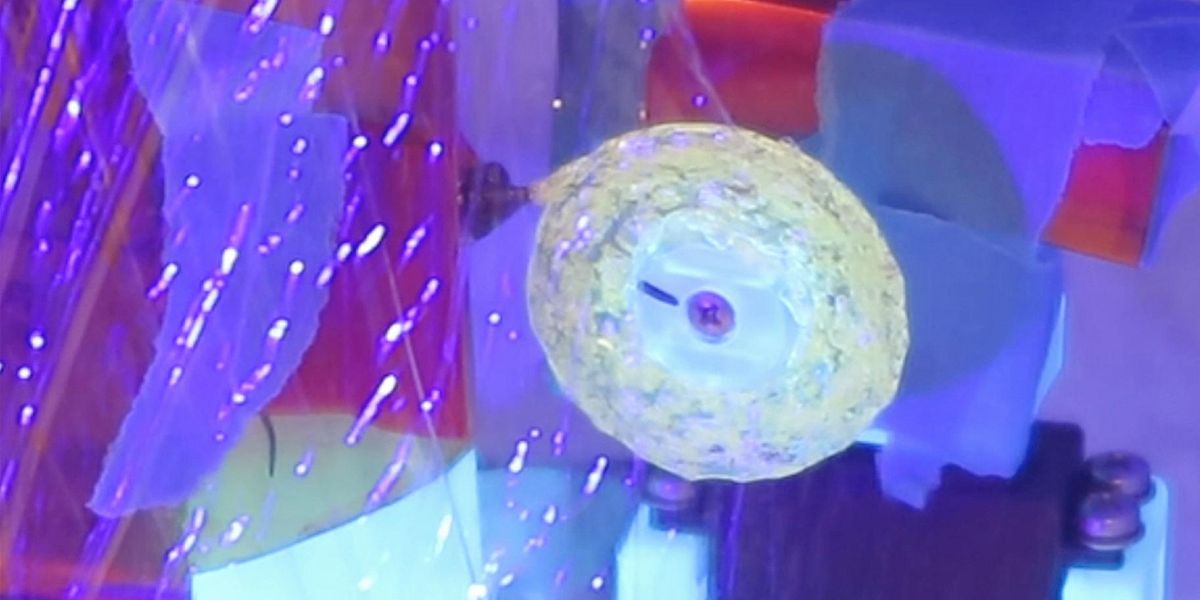
MERL has in fact developed an on-orbit, antenna 3D-printing technology that uses photosensitive resin, hardened by solar ultraviolet light. The new technique, the researchers say, potentially allows the dish to achieve high gain and wide bandwidth (which requires a large antenna), while still keeping the satellite that’s launched from Earth lightweight and small.

Printing the antenna on orbit solves another big problem, too: Satellites launched from the ground undergo enormous vibrational pressure during takeoff. So every part of the satellite—including the antenna dish and mount—has to be overbuilt to withstand the intense stress. This adds to the antenna’s weight and cost, and therefore the cost of the launch.

Of course, if the antenna is manufactured in space, none of these difficulties ever need bother the engineers designing the satellite.

As a case study, MERL researchers considered NASA and the European Space Agency’s Cassini-Huygens spacecraft—whose exceptionally large antenna measured 4 meters across and weighed 105 kilograms. If Cassini-Huygens (launched in 1997) could have substituted its oversize dish with an antenna that could have been fabricated in space, the spacecraft would have saved 80 precious kilograms of launch weight, translating to a launch-cost savings of 80 percent on the antenna and antenna-mount weight.
 
There are two ways to deal with improving ham radio receivers, or — for that matter — any sort of receiver. You can filter and modify the radio frequency including the radio’s intermediate frequency, or you can alter the audio frequency output. Historically, RF and IF techniques have been the most valued because rejecting unwanted noise and signals early allows the rest of the radio to focus on the actual signal of interest. However, audio filters are much easier to work with and until recently, DSPs that could handle RF frequencies were expensive and uncommon. However, [watersstanton] shows us how to make what could be the cheapest audio enhancer ever. It is little more than a modified cardboard box, and you can see and hear the result in the video below.

On the one hand, you shouldn’t expect miracles. On the other hand, you probably have box laying around and can try it in the next three minutes so why not give it a go? You can hear a bit of difference when using the box and not using the box.

In particular, you can tell, too, a difference in the position of the box. He also encourages you to experiment with different materials. He likens it to cupping your hand around your ear to direct sound flow. We’ve actually seen passive amplifiers for phones that are not much different than this.

We are firm believers that ham radio doesn’t have to be an expensive hobby. You can scrouge quite a bit of gear using almost nothing.
 
For 80 years, a class of antenna called electrically small antennas has been stymied by a seemingly insurmountable barrier. These antennas, which can receive signals with wavelengths that are much longer than the antennas themselves, are seemingly stuck with designs in which there is a trade-off between high bandwidth and efficiency.

Now, a new program by the U.S. Intelligence Advanced Research Projects Activity (IARPA) agency seeks ways to finally circumvent or overcome these historical limitations for electrically small antennas. Over the next four years, the research teams participating in the Effective Quantitative Antenna Limits for Performance (EQuAL-P) program will work through three phases of progressively more ambitious benchmarks in order to prove their ideas can work.

The simplest form of antenna is a dipole antenna, which is essentially just two pieces of wire placed end to end with a feed point in the middle. The length of this antenna is typically half the wavelength of the signal that is being received or transmitted, so a shortwave radio dipole working in the 20-meter band would be 10 meters long. An “electrically small” antenna is one that is significantly shorter than the wavelength of the signals it is designed for. These antennas typically take the form of small loops or patches.

The benefit of electrically small antennas is clear—as the name implies, they confer an advantage when space is at a premium. Satellites, for example, can use them to reduce mass and free up more space for other components.

But the trade-off with electrically small antennas is that as they get shorter, their bandwidth and radiation efficiency also shrink, eventually hitting something named the Chu-Harrington limit. This has meant that although such antennas have been in use for decades, they remain difficult to design and limited in their applicability. Historically, any attempts to widen the usable bandwidth have decreased these antennas' radiation efficiency even more, and vice versa. This is the problem the EQuAL-P program is aimed at.
 
Longtime Slashdot reader and tech historian, Kay Savetz, shares a blog post about the Internet Archive's efforts to build a library of amateur radio broadcasts. Here's an excerpt from the report: Internet Archive has begun gathering content for the Digital Library of Amateur Radio and Communications (DLARC), which will be a massive online library of materials and collections related to amateur radio and early digital communications. The DLARC is funded by a significant grant from the Amateur Radio Digital Communications Foundation (ARDC) to create a digital library that documents, preserves, and provides open access to the history of this community. The library will be a free online resource that combines archived digitized print materials, born-digital content, websites, oral histories, personal collections, and other related records and publications. The goals of the DLARC are to document the history of amateur radio and to provide freely available educational resources for researchers, students, and the general public. [...]

The DLARC project is looking for partners and contributors with troves of ham radio, amateur radio, and early digital communications related books, magazines, documents, catalogs, manuals, videos, software, personal archives, and other historical records collections, no matter how big or small. In addition to physical material to digitize, we are looking for podcasts, newsletters, video channels, and other digital content that can enrich the DLARC collections. Internet Archive will work directly with groups, publishers, clubs, individuals, and others to ensure the archiving and perpetual access of contributed collections, their physical preservation, their digitization, and their online availability and promotion for use in research, education, and historical documentation. All collections in this digital library will be universally accessible to any user and there will be a customized access and discovery portal with special features for research and educational uses.
 

Viestiliikenneharjoitus HF

18.11.2022 - 19.11.2022

Kurssilaiset voivat osallistua koulutukseen ja harjoitukseen Ylämyllyllä tai omilta radioamatööriasemiltaan.
PKALTSTO:n päällikön päätöksen (MS3021/11.02.2022) mukaisesti kurssille osallistuvat reserviläiset saavat kurssista kaksi (2) rinnasteista kertausharjoitusvuorokautta.
Ylämyllylle tulevilla kurssilaisilla on mahdollisuus majoittua Ylämyllyllä 18.–19.11. välinen yö.
 
Sähköautojen moottorit häiritsevät AM-signaalia. Sähköautojen lähellä havaittu myös voimakkaita HF-häiriöitä.

Ei ne moottorit mitään häiritse, mutta tehoelektroniikka joka moottoreita syöttää häiritsee kyllä. Enpä tiedä minkälainen EMC-suojaus sähköautojen taajuusmuuttajien ja moottoreiden välissä on, mutta jos se on tehty huonosti niin kyllähän sieltä säteileviä häiriöitä tulee.

Samaa asiaa kannattaa miettiä kun hommaa aurinkopaneleita + inverttereitä omaan taloonsa. Voi olla että sen jälkeen on häiriötaso sellainen että radiot ei paljon kuulu alemmilla taajuuksilla.
 
cs1.jpg


Äh, taas tuo klassinen virhe: ilmaisindiodin katodin tasavirtatie puutuu. C3:n rinnalle joku iso vastus, hemmetin iso kuristin tai kaikkein helpoiten, jätetään C2 pois ja annetaan (dynaamisten) kuulokkeiden hoitaa homma...
 
Heinäkuussa 1944 EP 4. Matti-partiot raportoivat Neuvostoliiton siirtävän joukkoja ja kalustoa pois kannaksen suurhyökkäyksestä. Tämän kunniaksi ehdotan että lauantaina 15. heinäkuuta pidämme reserviäisten Field Dayn ja otamme CW kusoja kuusen persukseen perustamaltamme Matti-asemalta.
 
Back
Top