APRS ..yms. radioamatööritoimintaa

Todella mahtava projekti


Clocks that read time via received radio signals have several advantages over their Internet-connected, NTP-synchronised brethren. The radio signal is ubiquitous and available over a fairly large footprint extending to thousands of kilometres from the transmitting antennae. This allows such clocks to work reliably in areas where there is no Internet service. And compared to GPS clocks, their front-end electronics and antenna requirements are much simpler. [Erik de Ruiter]’s DCF77 Analyzer/Clock is synchronised to the German DCF77 radio signal, which is derived from the atomic clocks at PTB headquarters. It features a ton of bells and whistles, while still being simple to build. It’s a slick piece of German hacker engineering that leaves us amazed.
http://hackaday.com/2017/03/22/well-engineered-radio-clock-aces-form-and-function/
 
Kriisi- ja turvaviestintäpalvelin käynnistyi Itä-Suomessa.

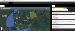
Radioharrastajavoimin toteutettu turvaviestintäserveri LARS 4.17 on nyt toiminnassa Kolin automaattisella tuvitoistinasemalla OH7RAC. Tarmon OH6ECF erityisesti kriisiviestinnän tarpeita ajatellen koodaama radioverkkojen kevyt tilannetieto- ja johtamisjärjestelmäsofta auttaa yhteyskatkostilanteen spontaaneja 'kaaosverkkoja' järjestäytymään toimiviksi tilapäisradioverkoiksi.

LARS toimii Kolin tuviasemalle asennetussa Raspberry-tietsikassa akkuvarmistettuna. Sen etusivun yhteysverkkokartalle voivat turva- ja kriisiviestintätilanteisiin varautumisesta kiinnostuneet lisätä omat radioasema- ja radioyhteystietonsa, ja päivittää niitä ajan tasalle.

Palvelimen radioverkkokartalle hyväksytään tavallisesti kaikki poikkeustilanteiden kriisiviestintään soveltuvat radioyhteydet. Näitä ovat lähes kaikki yleiset VHF- ja UHF-radiopuhelimet, kuten RHA68, LA, meri-VHF, elinkeinoelämän radiopuhelimet, PV:n pataljoonaradiot, PMR446, sekä radioamatöörien radiot.

Kolin turvaviestintätoistinta käytetään kehitysalustana tutkittaessa mahdollisuuksia luoda välttämättömimpiä pitkän maakuntakantaman hätä- ja kriisiviestintäyhteyksiä tavallisten radioverkkojen välille. Tämän kaltaisilla tuvitoistimilla on mahdollistaa muodostaa poikkeustilanteiden viestintää varten erillisistä VHF- ja UHF-radiopuhelimista verkkoja, hieman samaan tapaan matkapuhelintukiasemat muodostavat verkkoja kännyköistä.

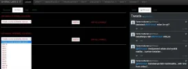
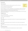
Oheiskuvissa on esimerkkejä Larsin etusivusta radioyhteys- ja paikkatietokarttoineen, viestipaneeleineen, etäohjausoptioineen, miniwikisivuineen ja chatteineen. Nämä Kolin Larsin sivut aukeavat osoitteessa: http://lars.dy.fi/ . Verkko-osoite voi myöhemmin muuttua.


2017-05-13 - OH7RAC turvaviestintäserveri LARS 4.17 Kolilla (c) OH7HJ.webp

2017-05-13 - Kolin OH7RAC turvaviestintäserverin LARS etäohjaus- ja viestipaneelit (c) OH7HJ.webp

2017-05-13 - Esimerkkejä Kolin turvaviestintäserverin LARS toiminnoista sen wikistä (c) OH7HJ.webp

Kriisiviestinnän kokeilualustana toimivan Kolin automaattisen tuvitoistinaseman ylläpitäjinä ovat enimmäkseen reserviläisistä ja radioharrastajista koostuvat vapaaehtoiset turvaviestintäaktiivit.

Linkkejä:

Välineitä poikkeusolojen viestinnän tarpeisiin: https://www.facebook.com/groups/1519431578386685/1743723752624132/
LARS-kokeilua, keskustelua ja esittelyä: https://www.facebook.com/groups/1519431578386685/permalink/1736189626710878/
LARS:in viestipaneeli: https://www.facebook.com/groups/1519431578386685/permalink/1712330015763506/

KRH-verkon prototyyppivaiheessa oleva "taktinen netti" on nyt saanut ytimekkään nimen LARS: https://www.facebook.com/groups/1519431578386685/permalink/1719743991688775/
FB:n turvaviestintäsivu: https://www.facebook.com/groups/108089039526164/
Kolin tuvitoistimen OH7RAC wikisivu: https://fi.wikibooks.org/wiki/Radiotaajuuskirja/OH7RAC

OH7RAC välittää sanomayhteyksiä osana radioamatöörien maailmanlaajuista digimodeverkkoa: http://guardian.no-ip.org:81/ChatNetwork.htm
Digimodeverkon BPQ32-palvelin OH7RAC-tuvitoistimella: http://koli.dy.fi:85/Node/Nodes.html
Turvaviestintätekniikan ketju kerhofoorumilla: http://www.oh7ab.fi/foorumi/viewtopic.php?f=15&t=225&start=70#p2274


- Juha​
 
Viimeksi muokattu:
soup-can-radio-featured.jpg

Pulaajan hätäradio

A standard early electronics project or kit has for many years been the construction of a small broadcast transmitter with enough power to reach the immediate area, but no further. These days that will almost certainly mean an FM broadcast band transmitter, but in earlier decades it might also have been for the AM broadcast band instead.

The construction of a small AM transmitter presents some interesting problems for an electronic designer. It is extremely easy to make an AM transmitter with a single transistor or tube, but it is rather more difficult to make a good one. The modulation has to be linear across the whole amplitude range, and its effect must not pull the frequency of the oscillator and cause FM distortion.

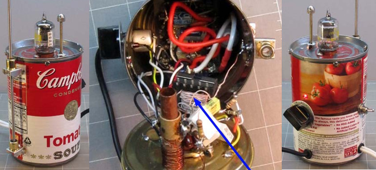
It’s a task [Joe Sousa] has tackled, with his one tube AM transmitter in a Campbell’s soup can. His write-up of the transmitter contains a full description of the problems he faced, and how his design overcomes them. His oscillator is a cathode follower, with the tube biased in class A mode to ensure as undistorted a sine wave oscillation as possible. Modulation is provided through the suppressor grid of the pentode tube he’s using.

The completed transmitter is mounted inside the iconic soup can, with the mains transformer mounted on a removable bottom plate. There is a provision for both loop and wire antennas to be connected.

It is probable that this transmitter falls under the so-called “Part 15” rules for unlicenced low-power broadcasting in the USA, however it should be borne in mind that not every territory has this provision. If you build this transmitter, make sure you’re not going to attract the interest of your local equivalent of the FCC.
http://hackaday.com/2017/05/28/a-tube-am-transmitter-in-a-soup-can/

http://www.radiomuseum.org/forum/hi_fi_am_transmitter.html
 

At first glance, the ColibriNANO SDR looks like another cheap SDR dongle. But after watching [Mile Kokotov’s] review (see video below), you can see that it was built specifically for software defined radio service. When [Mile] takes the case off, you notice the heavy metal body which you don’t see on the typical cheap dongle. Of course, a low-end RTL-SDR is around $20. The ColibriNANO costs about $300–so you’d hope you get what you pay for.

The frequency range is nominally 10 kHz to 55 MHz, although if you use external filters and preamps you can get to 500 MHz. In addition to a 14-bit 122.88 megasample per second A/D converter, the device sports an Altera MAX10 FPGA.


In addition to interfaces to different software packages, the dongle works with remote software. The idea is to put the dongle and an antenna somewhere advantageous (that is, high and radio-quiet) and then use a Raspberry Pi or similar computer to pipe signal over the Internet.

If you don’t want a dongle, we can endorse [Lukas’] build from scratch. If you are looking more for a getting started resource, check out what [Richard Baguley] had to say about SDR.
http://hackaday.com/2017/08/08/colibrinano-usb-sdr-receiver-reviewed/
 
If you’re a first responder — say, searching for someone lost in the outback, or underneath an avalanche — and you’re looking for someone with a radio beacon, what’s the fastest way to find that beacon? Getting up high would be a good idea, and if you’re using radio direction finding, you’ll want to be able to cover a lot of ground quickly if only to make the triangulation a bit easier. High and fast — sounds like the perfect opportunity for a drone, right?

[Phil Handley]’s Bloodhound project is an autonomous drone that can scan a wide area, listening for emergency beacons while alerting the search and rescue personnel. His test bed tricopter uses DT750 brushless outrunners controlled by 18A Turnigy Plush ESCs and powered by a 2200mAh LiPo. A metal-gear servo works the yaw mechanism. He’s also got a Pixhawk Autopilot, a ArduPilot flight controller, a NavSpark GPS, a software defined radio dongle, and a Raspberry Pi. He made the air frame out of wooden dowels, following RCExplorer’s tricopter design.

The next challenge involves radio direction finding, essentially creating Bloodhound’s foxhunting skills. It needs to be able to autonomously track down a signal by taking readings from multiple angles. In addition to finding lost skiers, [Phil] also envisioned Bloodhound being used to track other beacons, of course—such as wildlife transponders or errant amateur rockets.
http://hackaday.com/2017/08/24/hackaday-prize-entry-bloodhound-autonomous-radiolocation-drone/

https://hackaday.io/project/25995-bloodhound-autonomous-radiolocation-drone
 
The third version of [Henrik Forstén] 6 GHz frequency-modulated continuous wave (FMCW) radar is online and looks pretty awesome. A FMCW radar is a type of radar that works by transmitting a chirp which frequency changes linearly with time. Simple continuous wave (CW) radar devices without frequency modulation cannot determine target range because they lack the timing mark necessary for accurately time the transmit and receive cycle in order to convert this information to range. Having a transmission signal modulated in frequency allows for the radar to have both a very high accuracy of range and also to measure simultaneously the target range and its relative velocity.

Like the previous versions, [Henrik] designed a four-layer pcb board and used his own reflow oven to solder all the ~350 components. This process, by itself, is a huge accomplishment. The board, much bigger than the previous versions, now include digital signal processing via FPGA.

[Henrik’s] radar odyssey actually started back in 2014, where his first version of the radar was detailed and shared in his blog. A year later he managed to solve some of the issues he had, design a new board with significant improvements and published it again. As the very impressive version three is out, we wonder what version four will look like.
https://hackaday.com/2017/10/11/homemade-6ghz-radar-v3/
 

Most new hams quickly learn that the high-frequency bands are where the action is, and getting on the air somewhere between 40- and 160-meters is the way to make those coveted globe-hopping contacts. Trouble is, the easiest antennas to build — horizontal center-fed dipoles — start to claim a lot of real estate at these wavelengths.

So hacker of note and dedicated amateur radio operator [Jeri Ellsworth (AI6TK)] has started a video series devoted to building a magnetic loop antenna for the 160- and 80-meter bands. The first video, is an overview of the rationale behind a magnetic loop. It’s not just the length of the dipole that makes them difficult to deploy for these bands; as [Jeri] explains, propagation has a lot to do with dipole height too. [Jeri] covers most of the mechanical aspects of the antenna in the first installment; consuming a 50-foot coil of 3/4″ copper tubing means it won’t be a cheap build, but we’re really looking forward to seeing how it turns out.
https://hackaday.com/2017/11/01/jeri-builds-a-magnetic-loop-antenna/
 
Air Traffic Controllers use Automatic Dependent Surveillance-Broadcast (ADS-B) as an alternative to secondary radar to track aircraft. The ADS-B is transmitted by the aircraft and contains information such as GPS position, pressure, altitude, and callsign among other things at a 1090 MHz frequency, which can be decoded using any of a number of software tools.

[Mike Field] lives near an airport, and decided he wanted to peek into the tracking signals for fun. He turned to an RTL-based TV Dongle. Since the stock antenna was not cutting it, he decided to make one specifically for the 1090 MHz signal. His design is based on Coaxial Collinear Antenna for ADS-B Receiver by [Dusan Balara] which uses pieces of the coaxial cable cut to the right length. There are a number of calculations involved in determining the size of the cable, however, the hack in this design is the way he uses a USB based oscilloscope to measure the speed of RF waves inside the line in question.
https://hackaday.com/2017/12/06/measuring-hf-signal-speeds-in-a-diy-coaxial-collinear-antenna/
 
A distance record for LoRa transmission has been set that you probably won’t be able to beat. Pack up your gear and go home, nothing more to achieve here. At a superficial reading having a figure of 71,572 km (44,473 miles) seems an impossible figure for one of the little LoRa radio modules many of us have hooked up to our microcontrollers, but the story isn’t quite what you’d expect and contains within it some extremely interesting use of technology.

So the folks at Outernet have sent data over LoRa for that incredible distance, but they did so not through the little ISM band modules we’re used to but over a suitably powerful Ku-band uplink to a geostationary satellite. They are also not using the LoRaWAN protocols of the earthbound systems, but simply the LoRa modulation scheme. So it’s not directly comparable to terrestrial records such as the 702 km we reported on last year, and they are the first to admit that.

Where their achievement becomes especially interesting though is in their choice of receiver. We are all used to Ku-band receivers, you may even have one on your house somewhere for satellite TV. It will probably involve a parabolic dish with a narrow beam width and an LNB whose horn antenna is placed at its focus. It would have required some skill and effort to set up, because it has to be pointed very carefully at the satellite’s position in the sky. Outernet’s mission of delivering an information service with the lowest possible barrier to entry precludes the extra expense of shipping a dish and providing trained staff to align it, so they take a very different approach. Their receiver uses either an LNB horn or a small patch antenna pointing at the satellite, with none of the dishes or phased arrays you might be used to in a Ku-band installation.

You might wonder how such a receiver could possibly work with such a meagre antenna, but the secret lies in LoRa’s relatively tiny bandwidth as well as the resistance to co-channel interference that is a built-in feature of the LoRa modulation scheme. Even though the receiver will be illuminated by multiple satellites at once it is able to retrieve the signal and achieve a 30 kb/s data rate that they hope with technical refinements to increase to 100 kb/s. This rate will be enough over which to push an SD video stream to name just one of the several examples of the type of content they hope to deliver.
https://hackaday.com/2018/02/22/at-71572-km-you-wont-beat-this-lora-record/
 
Vapaaehtoiset rakensivat kaikessa hiljaisuudessa varajärjestelmän viranomaisten verkolle – ”Kustannustehokas keino turvata pelastustoiminnan johtaminen poikkeusoloissa”
Varve-varaverkkoa testattiin häiriötilanteen aikana, ja sen operaattorit olivat jatkuvassa valmiudessa.

POHJOIS-KARJALASSA on kaikessa hiljaisuudessa rakennettu varajärjestelmä viranomaisten viestinnässä käytettävälle Virve-verkolle.

Radioamatöörien ja pelastuslaitoksen rakentamaa koko maakunnan kattavaa verkkoa kutsutaan Varveksi. Se on lyhenne sanasta varaverkko.

Vuonna 2002 käyttöön otettu, kaikkien viranomaisten yhteiskäytössä oleva Virve-verkko osoitti haavoittuvuutensa vuodenvaihteen sähkökatkojen aikana, kun useita tukiasemia pimeni yhtä aikaa.

”Häiriöt eivät vielä haitanneet johtamista, eli paloasemat saivat yhteyden toisiinsa. Mutta kun lähdettiin maastoon, tuli ongelmia”, kertoo Pohjois-Karjalan pelastuslaitoksen valmiussuunnittelija Ville Leinonen.

Varve-varaverkkoa testattiin häiriötilanteen aikana, ja sen operaattorit olivat jatkuvassa valmiudessa.

”Ei ollut kaukana, että sitä olisi tarvittu käytännössä”, arvioi Pertti Karttunen Pohjois-Karjalan radiokerhosta.

IDEA Varve-verkosta syntyi, kun radioamatöörit rakensivat tilapäisiä viestintäverkkoja Radioamatööriliiton Turva-harjoituksia ja Puolustusvoimien sotaharjoituksia varten.

”Heräsi ajatus, että tukiasemat voisivat olla kiinteitä ja pysyviä”, Karttunen selittää.

Pelastuslaitos kiinnostui ideasta vuonna 2013. ”Oli havaittu, että Virve-verkossa voi olla häiriöitä”, Leinonen perustelee. Hän korostaa, että varaverkko on lisätyökalu.

”Emme ole luopumassa Virvestä. Haluamme edelleen kehittää myös sen häiriönsietokykyä.”

VARVE koostuu itse asiassa kolmesta eri verkosta. Puheverkko välittää puhetta ja sanomaverkko lyhyitä, tekstiviestin kaltaisia sanomia. Nämä verkot ovat jo toiminnassa. Rakenteilla oleva dataverkko pystyy tulevaisuudessa välittämään jopa videota reaaliaikaisesti.

Varve-verkon varmuus perustuu matalaan radiotaajuuteen, jolla on paljon Virve-verkkoa pidempi kantama. Tukiasemia koko maakunnassa on ainoastaan neljä. Niillä saadaan peittoa jopa naapurimaakuntien puolelle – Sotkamosta Savonlinnaan ja Kuopiosta itärajalle.

Tukiasemien sähköntarve on pienempi kuin kännykkämastoissa, joita myös Virve-verkko käyttää. Varavirta riittää sähkökatkon aikana kahdesta kolmeen vuorokautta, ja tyhjentyneet akut on helppo vaihtaa täysiin. Myös aurinkopaneelien ja tuuligeneraattorien käyttöä virtalähteenä tutkitaan.

VERKKOA operoivat radioamatöörit työskentelevät vapaaehtoispohjalta. Vastapalveluksena pelastuslaitoksen rakentamat tukiasemat ovat myös heidän harrastustoimintansa käytössä.

”Tämä on erittäin kustannustehokas keino turvata pelastustoiminnan johtaminen poikkeusoloissa”, Leinonen toteaa.

Maakunnallisen verkon ylläpito maksaa vain muutamia tuhansia euroja vuodessa. Sen rakentamiskulutkin ovat olleet vain 3 000–4 000 euroa vuodessa.

Leinonen muistuttaa, että vastaavaa VHF-radioteknologiaa oli pelastuslaitoksilla käytössä ennen Virve-verkon perustamista.

”Jälkikäteen ajatellen VHF olisi kannattanut säilyttää Virven rinnalla koko ajan.”

ALOITE varaverkon rakentamiseen ei tullut ylhäältäpäin, vaan koko verkko on ideoitu ja toteutettu ruohonjuuritasolla pelastuslaitoksen ja radioamatöörien kesken. Nyt Varve kiinnostaa muissakin maakunnissa.

”Etelä- ja Pohjois-Savossa kehitetään samantapaista verkkoa. Sieltä on käyty vierailemassa Varve-verkon harjoituksissa. Sielläkin radioamatöörit ovat mukana”, kertoo Pohjois-Karjalan radiokerhon aktiivi Antti Tiilikainen. Myös Pohjois-Suomessa on kiinnostuttu Varvesta.

Sisäministeriö pitää hanketta positiivisena. ”On hyvä, että on varajärjestelmiä ja vapaaehtoisuutta pystytään hyödyntämään”, toteaa ylitarkastaja Alpo Nikula.

Ministeriö ei kuitenkaan aio aktiivisesti edistää Varven laajentamista valtakunnalliseksi.

”Jos tämä olisi valtakunnallinen, kaikkialta pitäisi löytyä vapaaehtoisia. Myös jatkuvuus vapaaehtoisuuteen perustuvassa järjestelmässä voi olla ongelma. Löytyykö verkolle uusia ylläpitäjiä nykyisten jälkeen”, Nikula pohtii.

Ylitarkastaja muistuttaa, että Virve-verkko on edelleen ensisijainen viestintäväline ja sen varmuutta kehitetään.

”Virven häiriöistä on julkisuudessa voinut saada liian dramaattisen kuvan.”
Fakta
Radioamatööreistä apua kriiseissä

Radioamatöörit käyttävät toiminnassaan siihen varattuja radiotaajuuksia. Toiminta on luvanvaraista.

Yleensä harrastukseen liittyy kommunikatiivisuus, eli amatöörit ottavat toisiinsa yhteyttä radiolaitteiden avulla. Tämä erottaa heidät DX-kuuntelijoista, jotka bongaavat ja kuuntelevat radiolähetyksiä.

Radioamatööritoimintaan liittyy myös laitteiden ja mastojen rakentelu. Suomessa on noin 6 000 radioamatööriä.

Radioamatöörien viestintävälineitä on hyödynnetty eri puolilla maailmaa esimerkiksi myrskyjen ja maanjäristysten aiheuttamissa kriiseissä.
 
Osaavat tekijämiehet rakentavat ihkasen oikeaa suorituskykyä vapaaehtoisvoimin yhteistyössä viranomaisten kanssa.

Näin sen kuuluu toimia.
 
Mitenkäs paljon OneWeb -tyyppisistä ratkaisuista tulee olemaan hyötyä poikkeustilanteissa jolloin esimerkiksi tukiasemaverkko on osittain alhaalla? Merenalaiset kaapelit "pätkivät"? Ajattelen nyt siviilejä ja vapaata tiedonvälitystä:
http://www.oneweb.world/

Space-X:llä taitais olla suunnitteilla samantyyppistä.

Entä Outernet, alkoikos se taas toimia?
 
Viimeksi muokattu:
[K5ACL], aka [SignalSearch], recently brought his active receive loop antenna in off the roof to give it a checkup and perform any necessary maintenance. While it was in the shack, he took the opportunity to discuss how well it would perform indoors. The verdict? Not ideal. He’d mount it 50 feet away from the house if the HOA would let him.

Houses, and subsequently most ham shacks, are filled with noise sources that interfere badly with HF. So after spending a minute or so listening on an SDR, [K5ACL] demonstrates another use for this type of tightly-tuned antenna—as a noise detector.

The main culprit in [K5ACL]’s house is the ceiling light that’s right there in the shack. You can see the noise striping the waterfall as he turns it on and off. But the noise from the light is small potatoes compared to some other common household items, like those power line adapters that turn house wiring into networking cable. Those produce so much noise that even an active loop is really no match. Stay tuned after the break to watch [K5ACL] work the bands through the noise.

Loop antennas are great if you’re stuck in an apartment building or a congested city. They’re easy enough to make, whether you want a portable loop or a permanent installation.
https://hackaday.com/2018/03/01/finding-noise-with-an-antenna/
 
Radioamatöörit ovat saaneet viimeisen vuosikymmenen aikana ihmeitä aikaan uusilla DSP moodeilla. HF taajuudet on täynnä kohinaa ja suuritehoisia lähettimiä joten signaali on pitänyt puristaa ohuelle kaistalle ja sen on täytynyt olla erittäin vastustuskykyinen häiriöitä vastaan. Esin PSK31 puristi kaistanleveyden 100 Hz:n joka on puolet CW (morse) yhteyteen tarvittavasta kaistasta.

Olivia lisäsi hommaan virheenkorjauksen ja nyt näppikseltä-näppikselle yhteys saavutetaan mantereelta toiselle jopa 1 watin lähetysteholla.
https://en.wikipedia.org/wiki/Olivia_MFSK#Technical_details


Mitähän kaikkea saataisiin aikaan, jos Olivia MFSK ja joku Stream cipher yhdistettäisiin VHF linkkeihin.
 

It used to be homebrew ham gear meant something simple. A couple of active devices that could send CW. Maybe a receiver with a VFO. But only the most advanced builders could tackle a wide range SSB transceiver. Today, that goal is still not trivial, but it is way easier due to specialty ICs, ready access to high-speed digital signal processing, and advances in software-defined radio techniques. [Charlie Morris] decided to build an SSB rig that incorporated these technologies and he shared the whole process from design to operation in a series of nine videos.
https://hackaday.com/2018/06/06/homebrew-sdr-ham-radio-in-9-parts/
 

It’s been a project filled with fits and starts, and it very nearly ended up as a “Fail of the Week” feature, but we’re happy to report that the [Thought Emporium]’s desktop WiFi radio telescope finally works. And it’s pretty darn cool.

If you’ve been following along with the build like we have, you’ll know that this stems from a previous, much larger radio telescope that [Justin] used to visualize the constellation of geosynchronous digital TV satellites. This time, he set his sights closer to home and built a system to visualize the 2.4-GHz WiFi band. A simple helical antenna rides on the stepper-driven azimuth-elevation scanner. A HackRF SDR and GNU Radio form the receiver, which just captures the received signal strength indicator (RSSI) value for each point as the antenna scans. The data is then massaged into colors representing the intensity of WiFi signals received and laid over an optical image of the scanned area. The first image clearly showed a couple of hotspots, including a previously unknown router. An outdoor scan revealed routers galore, although that took a little more wizardry to pull off.
Linkin alla sarjan muut videot https://hackaday.com/2018/06/20/desktop-radio-telescope-images-the-wifi-universe/
 
Intialaiset ne osaa:
http://www.hfsignals.com/index.php/ubitx/

The µBITX is a general coverage HF SSB/CW transceiver kit with features you NEED for operating ease, convenience and versatility. It works from 3 MHz to 30 MHz, with up to 10 watts on SSB and CW with a very sensitive receiver. It features digital tuning, dual VFOs, RIT, CW Keyer and more. The µBITX is a general coverage HF SSB/CW transceiver kit with features you demand for operating ease, convenience and versatility. It features digital tuning, dual VFOs, RIT, CW Keyer and more.
 
Meiltä löytyy kotoa muutaman kympin radiopuhelimet. Taas toinen unohtui pojan leikeissä päälle yöksi. Aamu neljältä alkaa kuulumaan jotain lyhyitä radiokeskusteluita englanniksi. Liekö rekkakuskeja?
 
Back
Top