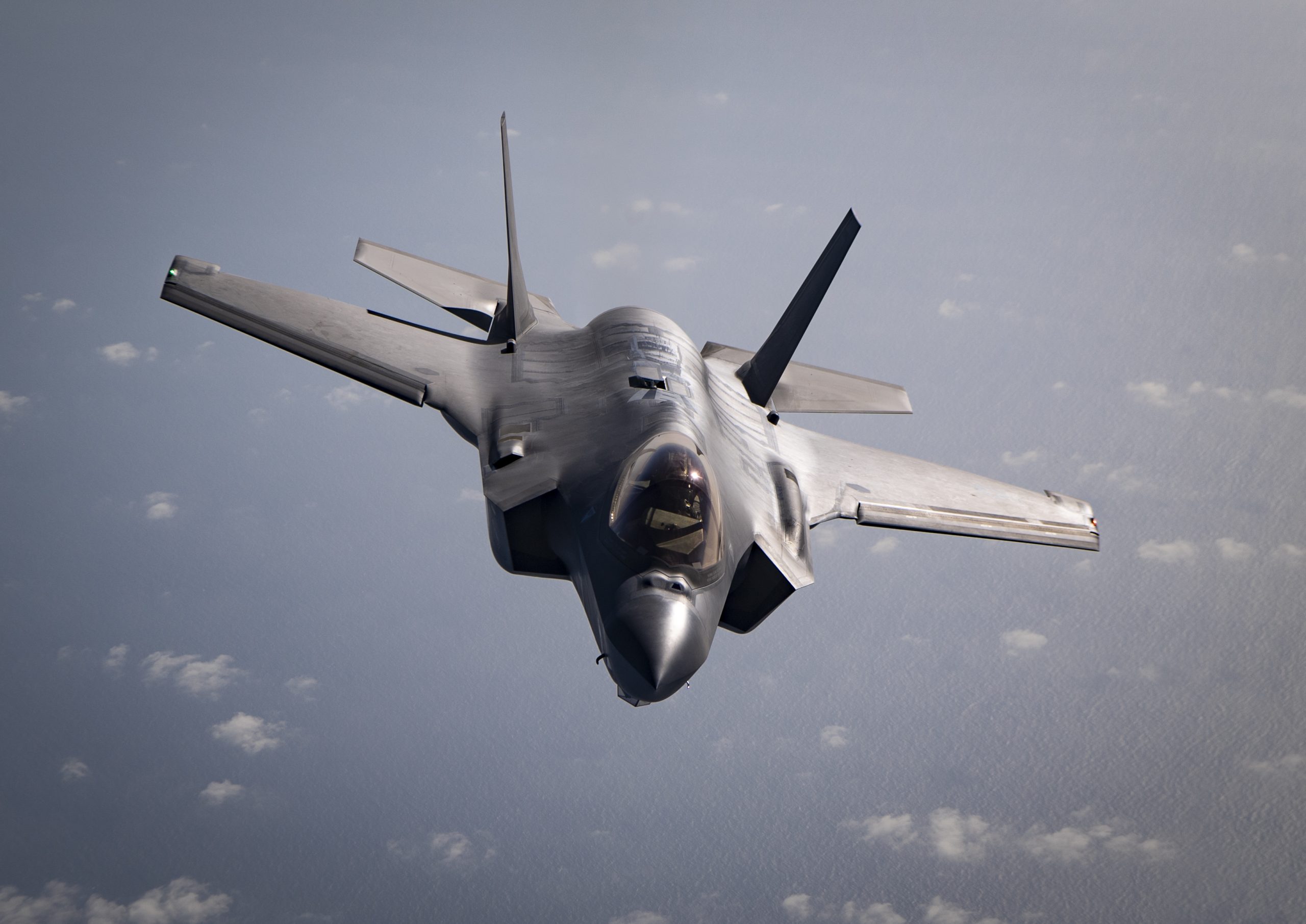
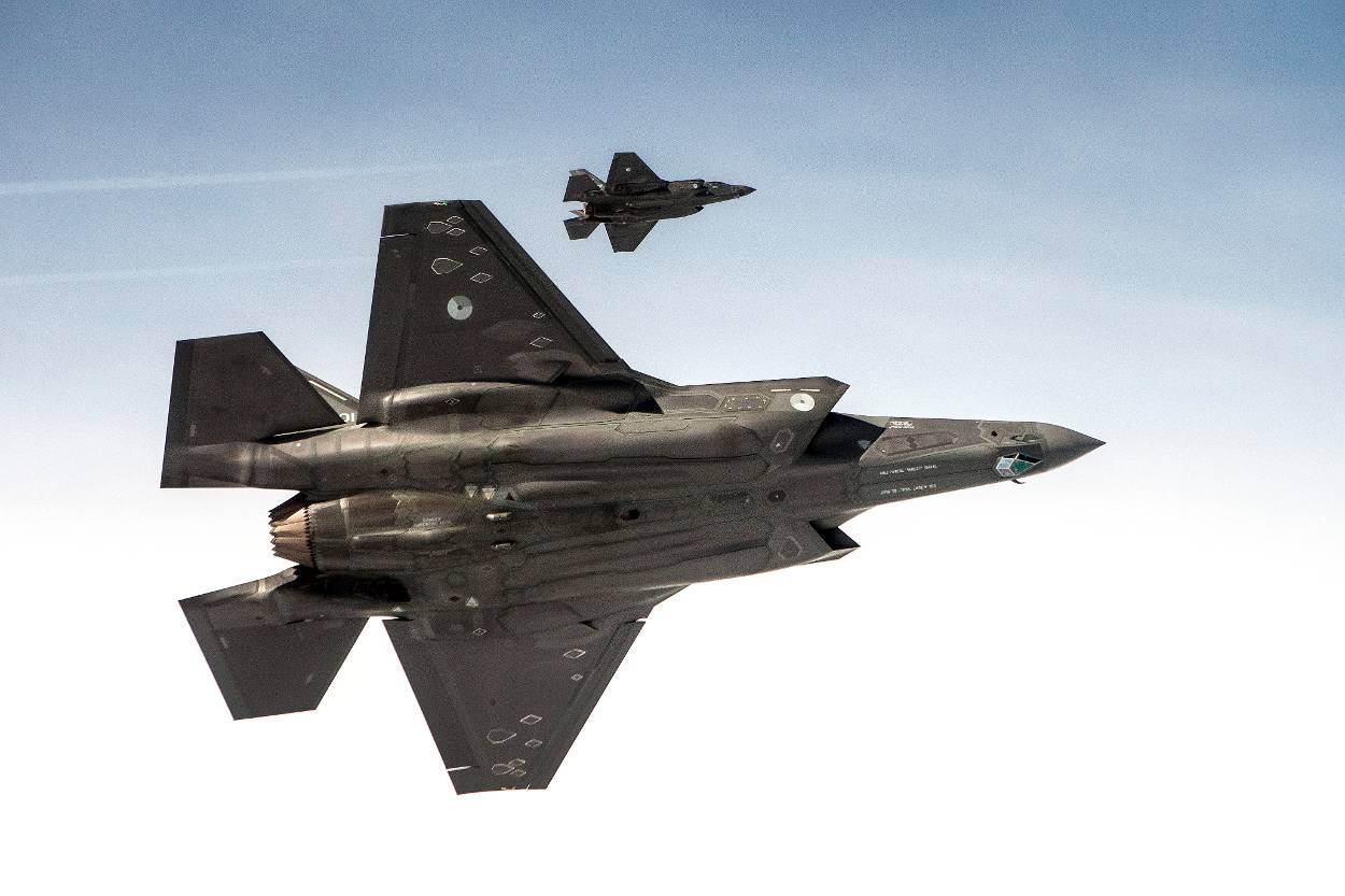
B. AN/ASQ-239 Electronic Warfare/Countermeasure System
The AN/ASQ-239 EW/CM system is an integrated suite of hardware and software. It is optimized and designed
to provide the F-35 with a high level of A/A and A/S threat detection and self-protection. It can search, detect, identify,
locate, and counter RF and IR threats. The EW system supports the application of electronic support measures (ESM)
through such functions as:
1) radar warning,
2) emitter geolocation,
3) multi-ship emitter location (including high-sensitivity states),
4) high-gain (HG) ESM,
5) HG electronic CM, and
6) HG electronic attack (EA) via radar MFA utilization.
The EW functions are designed for:
1) wide frequency coverage,
2) quick reaction time,
3) high sensitivity and probability of intercept,
4) accurate direction finding and emitter geolocation,
5) multi-ship geolocation, and
6) self-protection countermeasures and jamming.
The countermeasure subsystem provides multiple self-defense responses, including pre-emptive and reactive
techniques, based on available expendable payload and/or threat-specific self-protection plans. The EW/CM system
provides emitter tracks to the sensor fusion function, which fuses EW track reports and other sensors (e.g., radar and
DAS, off-board sensors) and displays the information to the pilot. The EW/CM system consists of the following
primary elements:
1) Band 3/4 apertures,
2) Band 3/4 aperture electronics,
3) centralized EW electronics (Racks 2A and 2B),
4) CM controller unit,
5) CM dispensers,
6) RF and digital interfaces with the MFA, and
7) digital-clock reference interfaces with the CNI system.
The installation locations of the EW/CM system-related equipment are depicted in (poistettu).
The EW system is common among the three F-35 variants, except for the forward Band 3/4 arrays, which
employ longer elements for the F-35C Carrier Variant (CV). Also differing, the distance between the inboard and
outboard arrays is less on the CV variant due to the wing fold. In addition to the EW Band 3/4 apertures, the radar
MFA is employed to support EW functions. There are growth provisions allocated for Band 5 radar warning such that
Band 5 apertures, aperture electronics, and the Band 5 switch can be incorporated into the EW subsystem architecture.
The EW apertures comprise six multi-element antenna array sets covering portions of the Band 3 and Band 4
frequency spectrum, along with both vertical and horizontal polarization. All the arrays have azimuth (AZ)-only
designs that do not rely on the use of elevation (EL) arrays. The passive array assemblies use a traveling wave-notch
element approach designed to balance gain, polarization, field of view (FOV), and radar cross-section features. Each
Band 3/4 aperture feeds an aperture electronics module that amplifies and passes the detected RF signals from the
apertures. It does this through a switch matrix and tuners that distribute the RF to a set of wideband EW receivers
(EWRs). The switch matrix also receives RF signals from the radar MFA when tasked to support HG modes.
The EWR suite consists of 12 wideband receivers grouped into three integrated sets of four channel receivers. The
wideband receivers take in RF energy and convert the data into digital information via a set of high-speed analog-todigital converters for processing.
Each EWR performs initial data processing and generates pulse parameter reports that are sent to the EW controller/preprocessor.
The processor then provides further signal processing and algorithms to support all EW activities.
Various intelligence products combine to produce an electronic intelligence (ELINT)
database in a preplanned mission data file. This data file provides the system with the necessary parametric
descriptions of the emitters of interest for emitter identification and scan schedule operations.
EW system testing was performed in a buildup fashion of increasingly complex integration into the rest of the
avionics system. The integration began with stand-alone laboratory testing isolated from the rest of the avionics system
and progressed through a Sabreliner T-39-based flying testbed. From there the EW system was integrated into the
F-35 avionics suite to continue both laboratory testing and dynamic open-air testing on the Lockheed Martin CATB.
After the system was proven on the CATB it progressed to full airborne testing on the F-35. The buildup timeline for
the EW system is shown in Fig. 5.


